Concrete is a mixture of cement, fine aggregate (Sand), coarse aggregate(Gravel), admixture and water.
It depends upon the ratio of concrete that which ingredients use in which proportion. Normally the percentage (%) of ingredients use in concrete are given below.
Ingredients (%)
Range of Percentage (%) of each ingredients are given below:
A long vertical member normally subjected to an axial compressive load is called Column.
Types of Column
There are three types of Columns, based on their nature of failure:
1) SHORT COLUMN
The length of this type of column is less than 8 times the least lateral dimension. The type of failure in this type of column is due to direct crushing only. Bending or buckling plays much less important role.
2) MEDIUM COLUMN
The length of this type of column varies from 8 to 10 times the least lateral dimension. In this type of column, failure may occur partly due to crushing and partly due to buckling.
3) LONG COLUMN
The length of this type of column varies from 30 times their least lateral dimension. In this type of column, failure is due to buckling.
In addition to Mixing, Pouring and Compaction, the concrete strength mainly depends on the following factors:
Factors Affecting Concrete Strength
(1) Water-Cement Ratio (W/C)
To decrease in W/C will increase the strength of concrete. Normally water-cement ratio is 0.45-0.55 for normal concrete.Affects of W/C on Concrete Strength
(2) Aggregate-Cement Ratio
To decrease in Aggregate-Cement Ratio increase the strength of concrete upto numerical value of 2, further decrease of Agg/Cement may cause decrease in strength on concrete.
(3) Aggregate
The concrete strength is affected by
Aggregate Strength
Surface Texture
Grading
Maximum size of aggregate in concrete
(4) Curing
Prolonged moist curing results in getting highest concrete strength.
Rate Of Strength Gain by Concrete
The ACI code proposes the rate of strength gain for concrete in which type-I concrete was used at 70F° by the following Equation
fc’(t)= fc'(28)(t⁄ 4+0.85t)
In the above Equation t= Time in days fc’= Compressive strength at age “t” in days
Variation in Strength of Concrete
The strength variation of finished concrete depends on
Definition: The concrete is extensively applied as construction materials and several mixes of fixed ratio are now being used with concrete to retain adequate strength. These mixes are known as nominal mixes.
Under normal situation, it contains margin of strength over that specified.
Nominal mix concrete is applied for concrete of grades M5, M7.5, M10, M15 and M20.
Ratios of ingredients in nominal mixes
Concrete Grade
Mix Ratio
Compressive Strength
M7.5
1 : 4 : 8
7.5 MPa
M10
1 : 3 : 6
10 MPa
M15
1 : 2 : 4
15 MPa
M20
1 : 1.5 : 3
20 MPa
With 1:1.5:3 ratio, it signifies that these should be measured as 1 kg of cement, 1.5 kg of fine aggregate and 3 kg of coarse aggregate.
But, usually they are selected on the volume basis and multiplied with 1.55 constant (in Nominal Mix Concrete Calculation) to obtain the bulk volume of the material.
Design Mix
Definition: The concrete mix created under quality control on the basis of the strength, durability and workability in the laboratory tests is known as the design mix.
Prior to arrive at the mix ratio, several other factors should be taken into consideration which range from accessibility of equipment for compaction, curing process selected, type of cement, quality of fine and course aggregate etc.
The design mix or controlled mix is extensively utilized for different types of vital structures due to superior strength; leaner mixed with consequent economy and improved quality.
In design mix, the concrete is formed in weight basis especially for greater volume where the load is vital. It is required to examine each and every property of the ingredients mentioned below.
Weight of each ingredient • Brands • Mix Proportions • Type of exposure • Properties of Cement: Initial & Final Setting Time, Specific gravity, Cement Grades
• Properties of Fine & Coarse Aggregates – Particle Size, Silt Content, Unit Weight, Fineness Modulus, Crushing Value
Standard Grade of Concrete
M25
1 : 1 : 2
25 MPa
3625 psi
M30
Design Mix
30 MPa
4350 psi
M35
Design Mix
35 MPa
5075 psi
M40
Design Mix
40 MPa
5800 psi
M45
Design Mix
45 MPa
6525 psi
High Strength Concrete Grades
M50
Design Mix
50 MPa
7250 psi
M55
Design Mix
55 MPa
7975 psi
M60
Design Mix
60 MPa
8700 psi
M65
Design Mix
65 MPa
9425 psi
M70
Design Mix
70 MPa
10150 psi
On the basis of the above things, the mix design will be set up as per requirements and then examined with trial mix. As soon as the trial mix is examined and passed on 7th & 28th Days for compressive strength, then it will be considered for construction purposes.
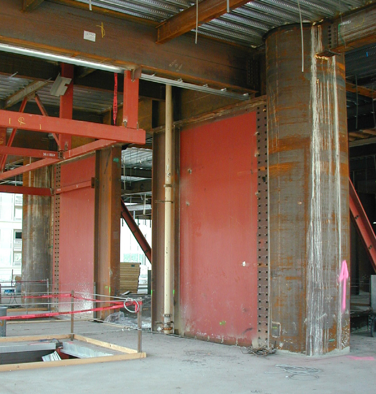
Shear wall is a structural member in a reinforced concrete framed structure to resist lateral forces (mostly in plan) such as wind forces and earthquake forces. OR Shear walls are the resistant element to the horizontal forces (in plan forces)acting on it due to severe winds or earthquake.
Structural Mechanism for Shear walls
In concrete buildings construction, a rigid vertical diaphragm capable of transferring lateral forces from exterior walls, floors, and roofs to the foundation in a direction parallel to their planes. Examples are the reinforced-concrete wall or vertical truss. Lateral forces caused by wind and earthquake, and uneven settlement loads. These forces can shear a building apart. Reinforcing a frame by attaching or placing a rigid wall inside it maintains the shape of the frame and prevents rotation at the joints. Shear walls are especially important in high-rise buildings. Structural mechanism of shear walls
Types of Shear Walls
Based on type of material used, shear walls are classified into following types.
Reinforced Concrete Shear Wall
Concrete Block Shear Wall
Steel Shear Wall
Plywood Shear Wall
Mid-Ply Shear Wall.
1) Reinforced Concrete Shear Wall
Reinforced concrete shear walls are widely used shear walls for residential buildings. The reinforcement is provided in both horizontal and vertical directions. But at the end of each wall, bars are closely spaced and anchored. So, the end zones of RC shear wall is called as boundary elements or barbells.
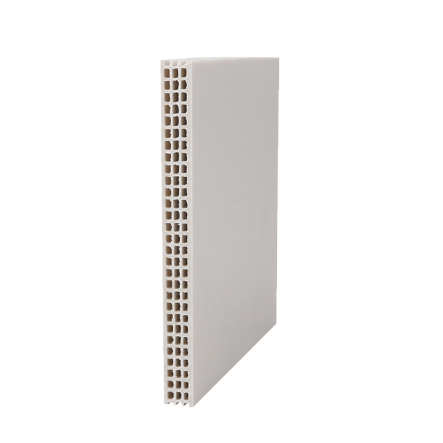
2) Concrete Block Shear Wall
Concrete block shear walls are constructed using Hollow concrete blocks along with Steel reinforcement bars. Reinforcement is generally used to maximize the effect of concrete block masonry against seismic loads.
Steel shear wall consists of a steel plate wall, boundary column and horizontal floor beam. The action of steel shear wall is more like a plate girder. Steel plate wall acts as web of plate girder, boundary columns acts as flanges and horizontal beams acts as stiffeners of plate girder.
Plywood shear walls are traditional type walls which are also called as timber shear walls. It consists of plywood sheets and studs. Plywood sheets transfer shear force while studs resists the tension or compression.
Plywood shear wall
5. Mid-Ply Shear Wall
Mid-ply shear wall is an improved version of normal plywood shear wall. In this case, extra plywood sheet is arranged at the center of normal plywood wall and series of pairs of studs are positioned on the both sides of mid-ply. Studs joint the mid-ply with outer plywood sheets standard shear walls and lateral load carrying capacity is higher for mid-ply shear walls.
Arrangement of Shear Walls in a Building
Structurally, the best position for the shear walls is in the centre of each half of the building.Location and Geometry Of shear walls.
Location of Shear Walls in Buildings
Limitation for Shear Walls:
Limitations on the use of building,
Adverse effects on the behavior of non-load bearing elements,
Degradation in the appearance of the building,
Discomfort for the occupants.
Generally, the relative lateral deflection in any one storey should not exceed the storey height divided by 500.
The three(3) major Design Philosophies used while designing of RCC, Steel or any type of Civil Engineering Structures are discussed here:
ASD (WSD or WSM)
ULM (USD)
LRFD (LSD or LSM)
(1) ASD (WSD)
Allowable Stress Design (ASD) also called Working Stress Design/method (WSD) is basically Allowable Strength Design. In this method we apply a Factor of Safety (FoS) on ultimate strength of the material as whole and compare the results with the actual load that actually to be applied during the life span of the structure, if actual load < allowable load then the design is OK. This method only satisfy the serviceability of the structure or Serviceability Limit State (SLS).
Drawbacks
ASD method uses only the elastic region of stress-strain curve of materials due to which most of the strength acts as a reserve.
ASD gives an uneconomical dimensions of the structural element.
ASD doesn’t show any sign about collapse of structure, it means doesn’t satisfy the Ultimate Limit State.
ASD uses only material strength reduction factors in the form of FoS: Which are Given below:
Factor of Safety (FoS) for Concrete= 3
Factor of Safety (FoS) for Steel= 1.78
Stress-Strain Curve for Concrete
(2) ULM (USD 0r Load factor)
Ultimate Load Method (ULM) or Ultimate Strength Design (USD) or Load Factor is the design philosophy of design structures in which load increasing factor is used while calculating different loads combinations and these factors generally (>1) to increase loading so is to adjust the uncertainties occurring in load applications. Some Load Combination According to ASCE and UBC-97 are Listed here:
ASCE Load Combinations
1.4D
1.2D + 1.6L + 0.5(Lr or S or R)
1.2D + 1.6(Lr or S or R) + (L or 0.5W)
1.2D + 1.0W + L+0.5(Lr or S or R)
1.2D + 1.0E + L +0.2S
0.9D + 1.0W
0.9D + 1.0E
UBC-97 Load Combinations
1.4D
1.2D + 1.6L +0.5 (Lr or S)
1.2D +1.6 (Lr or S) + (f1L or 0.8W)
1.2 D + 1.3W + f1L + 0.5 (Lr or S)
1.2 D + 1.0E + (f1L + f2S)
0.9D ± (1.0E or 1.3W)
“Load factor is the ratio of ultimate strength to the service loads“
The ULM makes it possible to consider the effects of different loading acting simultaneously thus solving the shortcomings of WSM (WSD). As the ultimate strength of the material is considered we will get much slender/thinner sections for different elements of the structures e.g columns, beams etc. In this method we use the non-linear method of stress-strain curves for concrete and steel.
Stress-Stain Curve for Steel Rebar
Drawbacks
This method doesn’t satisfy the Serviceability Limit State (SLS).
This method gives very thin sections of members which is vulnerable to severe cracks and damaged.
This method only consider load factors while ignoring the strength of materials.
(3) LRFD (LSD or LSM)
Load and Resistance Factor Design(LRFD) or Limit State Method/Design (LSM or LSD) is the most advanced method while design any civil engineering structures. It considered both factored loads and material strength reduction factors partially.
There are Two Limit States which is satisfied in LRFD (LSM) Method:
Ultimate Limit State: It considers strength, overturning, fatigue, sliding etc.
Serviceability Limit State: It Considers Cracks width, deflection, vibration etc.
This method use to multiply partial safety factors for required safety at ultimate load and serviceability at working load.
Partial Safety Factor for Materials:
The strength of concrete in actual structure is taken as (0.67*characteristic strength), i.e 0.67fck. The partial safety factor for (Ultimate limit state) for concrete is 1.5 and that for steel is 1.15. The value for concrete higher because it has more variability and uncertainties compared to steel. The partial safety factor ( for serviceability limit state) for concrete and that for steel is taken is 1. This is taken unity as we are interested in estimating the actual deflections and crack widths during service loads.
Partial Safety Factor for Loads:
Various load Combinations are used and it may be different in different design codes.
For Ultimate Limit States:
UL= 1.5(DL+LL)
UL=1.5(DL+QL) or 0.9DL+1.5QL (QL: Earthquake/Wind Load)
UL=1.2(DL+LL+QL) (1.2 because the probability of three loads reaching its peak together are less)
For Serviceability Limit States:
SL= 1.0 (DL+LL)
SL=1.0 (DL+QL)
SL=1.0DL+0.8LL+0.8QL
The load factor is taken as 0.8 in the third case as the probability of wind load or earthquake load acting with the peak of live load is less. For all other cases we consider the safety factor is 1.0 because we consider the serviceability of structure here.
So Why LRFD/LSM Design Philosophy is more reliable?
LRFD/LSM is a more reliable and statistical based method for predicting both loads and material strengths.
Whereas the allowable stress safety factors were based on engineering judgement and past experiences.
This method gives you an economical, safer & serviceable structural elements/members.
The shortcomings in the previous methods were addressed and rectified here on a more rational basis.
Structural Systems of Slabs and Its Types, Purpose
Structural System
Structural system in building construction, the particular method of assembling and constructing structural elements of a building so that they support and transmit applied loads safely to the ground without exceeding the allowable stresses in the members.
Types and Purpose of Structural System
There are various types of structural system used in design of Civil Engineering Structures:
(1) FLAT PLATE SYSTEM
A flat plate is a slab system in which the slab of uniform thickness is supported directly on columns. This system is economical for short and medium span (15′ – 25′) and for normal loads. In this slab punching shear is the failure criteria.
(2) FLAT SLAB SYSTEM
It is a beam less slab system with drop panel or column capitals or both is known as Flat Slab System. This system is economical with span ranging from (20′ to 30′). The drop panel is thick part of slab around the column, while column capitals is head of increased size.
(3) BEAM SUPPORTED SLAB SYSTEM
This system consists of Reinforced Concrete beams in one or both direction cast monolethically with slab. This system is suitable for long spans normally 30′ and for intermediate to heavy loads.
Slab Structural Systems
(4) BEAMS AND GIRDER SLAB SYSTEM
It consist of series of parallel beams supported at the ends by girder which is then connected to columns. This system can be adopted for any type of loads and spans.
(5) ONE WAY JOISTS SLAB
This consists of monolethic combinations of regular placed ribs and a top slab in one direction. This system is economical for the (30′ – 50′) span.
Structural Slabs Systems
(6) TWO WAY JOIST SLAB
It is also called “waffle Slab System” which consist of evenly spaced joist in both direction with a top slab.
Two-Way Joist or Waffle Slab
(7) COMPOSITE SLAB SYSTEM
In this system columns, beams and girders consists of structural steel while the floor RCC slabs. The spacing of beam is normal 6′ – 8′. Steel ratio with respect to concrete increase in beams, increased upto 50% that’s why it is so called composite slab system.
(8) PRESTRESSED SLAB SYSTEM
It can be a pretension or post-tension slab system in which the hollow conduits are provided in slab through which steel tendons are placed. The tendon are tension after the concrete has gained sufficient strength or before the concreting. In this type of slab the column and beams an normally RCC member.
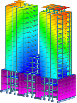
It is a method or tool by which we find out how a structure or a member of a structure behaves when subjected to certain loads.
In other words finding out internal forces (axial force, shear force, moment), stress, strain, deflection etc in a structure under applied load conditions.
Structural analysis and Design
Whenever design any structure first of all we Analyze the structure either manually or through software or may be both. So there is number of methods of Structural Analysis. Mainly these methods are used to analyze indeterminate structures ( no. of reactions more than equilibrium equations) In this article we will discuss just the name of methods.
Methods of Analysis
There are two main Methods which have further divided into different methods. There is some limitations while analysing any structure that’s why you have to chose the most appropriate method while analysing any structure.
Exact Methods
Approximate Methods
(1) Exact Methods
It is the most accurate methods while analyzing any indeterminate structures. It is also called accurate method. In this method the material property called Modulus of Elasticity (E) and geometric property called Area Moment of Inertia (I) of the materials are required.
This method is further subdivided into two methods. We will discuss each methods in detail in the next article.
Force Methods
Displacement Methods
1. Force Methods
Three Moment Theorem
Flexibility Matrix
Virtual Work/Unit Load Method
Strain Energy Method
Methods of Consistent deformation
Column Analogy
Minimum Potential Energy Method
Castigliano’s Method etc
2. Displacement Methods
Moment Distribution Method
Stiffness Matrix Method
Slope Deflection Method
Kani’s Method etc
(2) Approximate Methods
In this method the material property called Modulus of Elasticity (E) and geometric property called Moment of Inertia (I) of the materials are not required. In this method indeterminate structures first convert to determinate structures and then analysed using equation of equilibrium.
The following three methods normally used in analysing.